Part 1: VMware vSphere 6.7 Configuration Guide Phần 1: Hướng dẫn Cấu hình VMware vSphere 6.7
Topology Diagram & Planning
Sơ đồ Quy hoạch & Cấu trúc mạng
1.1 Topology
1.2 IP and Port Planning 1.2 Quy hoạch IP và Cổng kết nối
Below is the designated IP addressing scheme and port allocation for the infrastructure. Dưới đây là bảng quy hoạch địa chỉ IP và phân bổ cổng cho hạ tầng.
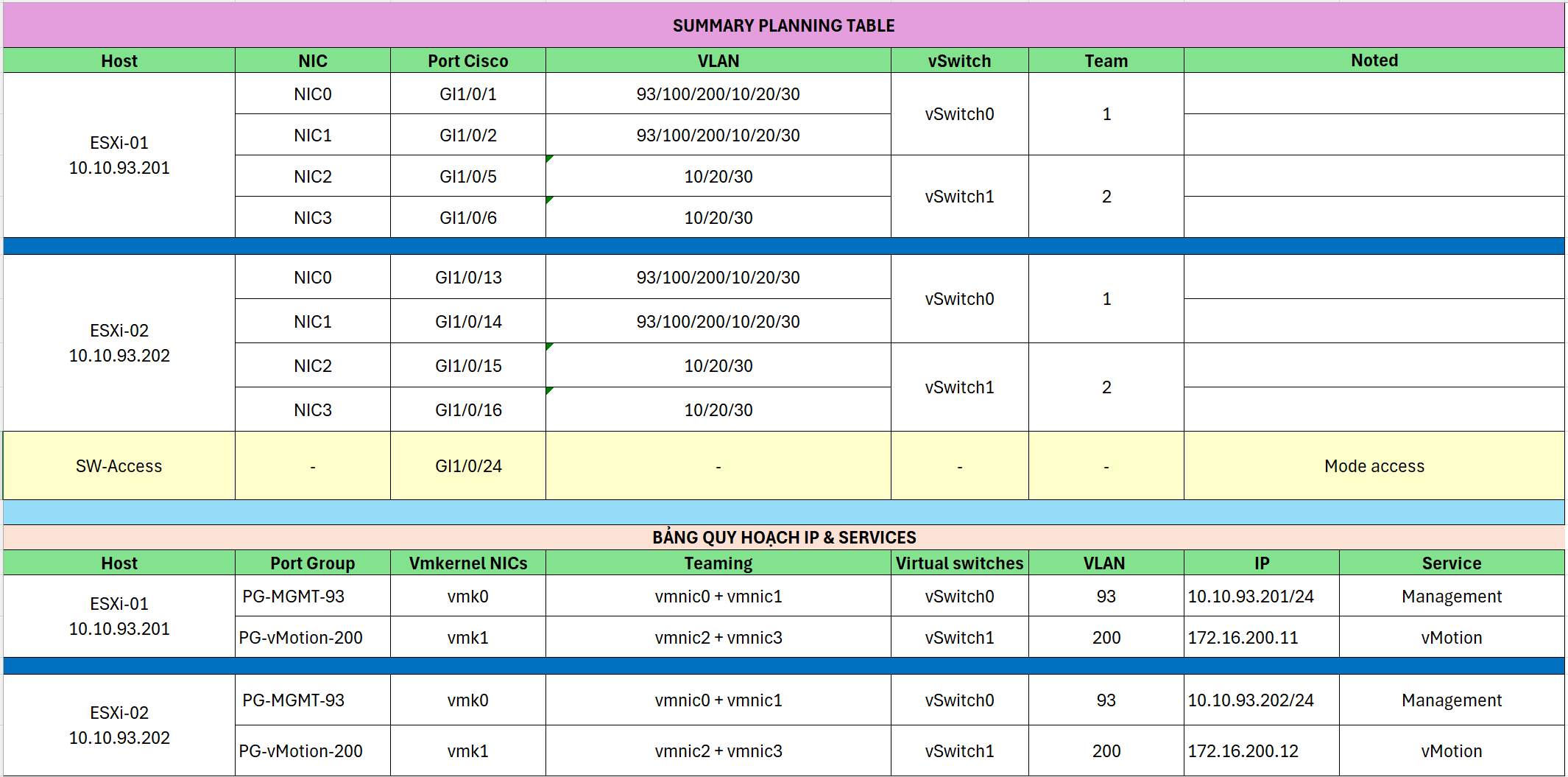
Cisco Switch Configuration
Cấu hình Switch Cisco
1. Configure IP and VLAN 93 1. Cấu hình IP và VLAN 93
Setup Management VLAN and assign IP for Layer 3 Switch. Thiết lập VLAN Quản trị và gán IP cho Switch Layer 3.
Switch# conf t
Switch(config)# vlan 93
Switch(config-vlan)# name MGMT
Switch(config-vlan)# exit
Switch(config)# interface vlan 93
Switch(config-if)# ip address 10.10.93.10 255.255.255.0
Switch(config-if)# no shutdown
Switch(config-if)# ip default-gateway 10.10.93.1
Verify configuration: Kiểm tra lại cấu hình:
Switch# show ip interface brief2. Configure Switch Access Mode 2. Cấu hình chế độ Access cho Switch
Configure uplink port connected to Access Switch. Cấu hình cổng uplink kết nối tới Access Switch.
Switch(config)# interface gi1/0/24
Switch(config-if)# description UPLINK-TO-ACCESS-SWITCH
Switch(config-if)# switchport mode access
Switch(config-if)# switchport access vlan 93
Switch(config-if)# spanning-tree portfast
Switch(config-if)# no shutdown
Switch(config-if)# end
Switch# write
Check port status: Kiểm tra trạng thái cổng:
Switch# show ip int brief| InterfaceCổng | IP-AddressĐịa chỉ IP | StatusTrạng thái | ProtocolGiao thức |
|---|---|---|---|
| Vlan93 | 10.10.93.10 | up | up |
| GigabitEthernet1/0/1-23 | unassigned | down/up | down/up |
| GigabitEthernet1/0/24 | unassigned | up | up |
3. Create Telnet User 3. Tạo tài khoản Telnet
Configure remote access for administrators. Cấu hình truy cập từ xa cho quản trị viên.
Switch# conf t
Switch(config)# hostname SW3750
SW3750(config)# ip domain-name doanh.local
SW3750(config)# line vty 0 4
SW3750(config-line)# login local
SW3750(config-line)# transport input telnet
SW3750(config-line)# exit
SW3750(config)# username admin privilege 15 secret ********
SW3750(config)# end
SW3750# write
4. Configure ESXi-01 Switch Ports 4. Cấu hình cổng cho ESXi-01
Configure ports connecting to ESXi-01 server. Cấu hình các cổng kết nối đến máy chủ ESXi-01.
NIC-0 & NIC-1 (vSwitch0):
SW3750(config)# interface range Gi1/0/1-2
SW3750(config-if-range)# description ESXi01-vSwitch0
SW3750(config-if-range)# switchport trunk encapsulation dot1q
SW3750(config-if-range)# switchport mode trunk
SW3750(config-if-range)# switchport trunk allowed vlan 93,100,200,10,20,30
SW3750(config-if-range)# spanning-tree portfast trunk
NIC-2 & NIC-3 (vSwitch1):
SW3750(config)# interface range Gi1/0/5-6
SW3750(config-if-range)# description ESXi01-vSwitch1
SW3750(config-if-range)# switchport trunk encapsulation dot1q
SW3750(config-if-range)# switchport mode trunk
SW3750(config-if-range)# switchport trunk allowed vlan 10,20,30
SW3750(config-if-range)# spanning-tree portfast trunk
5. Configure ESXi-02 Switch Ports 5. Cấu hình cổng cho ESXi-02
Configure ports connecting to ESXi-02 server. Cấu hình các cổng kết nối đến máy chủ ESXi-02.
NIC-0 & NIC-1 (vSwitch0):
SW3750(config)# interface range Gi1/0/13-14
SW3750(config-if-range)# description ESXi02-vSwitch0
SW3750(config-if-range)# switchport trunk encapsulation dot1q
SW3750(config-if-range)# switchport mode trunk
SW3750(config-if-range)# switchport trunk allowed vlan 93,100,200,10,20,30
SW3750(config-if-range)# spanning-tree portfast trunk
NIC-2 & NIC-3 (vSwitch1):
SW3750(config)# interface range Gi1/0/15-16
SW3750(config-if-range)# description ESXi02-vSwitch1
SW3750(config-if-range)# switchport trunk encapsulation dot1q
SW3750(config-if-range)# switchport mode trunk
SW3750(config-if-range)# switchport trunk allowed vlan 10,20,30
SW3750(config-if-range)# spanning-tree portfast trunk
Adjust VLAN settings in 2 ESXi hosts
Điều chỉnh VLAN trên 2 host ESXi
Perform directly on the physical server console (DCUI) or virtual console (iDRAC/iLO). Thực hiện trực tiếp trên giao diện console của máy chủ vật lý (DCUI) hoặc qua console ảo (iDRAC/iLO).
- Press F2 and log in with the root account.
- Select Configure Management Network.
- Select VLAN (Optional).
- Enter VLAN ID: 93.
- Press Enter to confirm.
- Press Esc and select Y (Yes) to save and restart network services.
- Nhấn F2 và đăng nhập bằng tài khoản root.
- Chọn Configure Management Network.
- Chọn VLAN (Optional).
- Nhập VLAN ID: 93.
- Nhấn Enter để xác nhận.
- Nhấn Esc và chọn Y (Yes) để lưu và khởi động lại dịch vụ mạng.
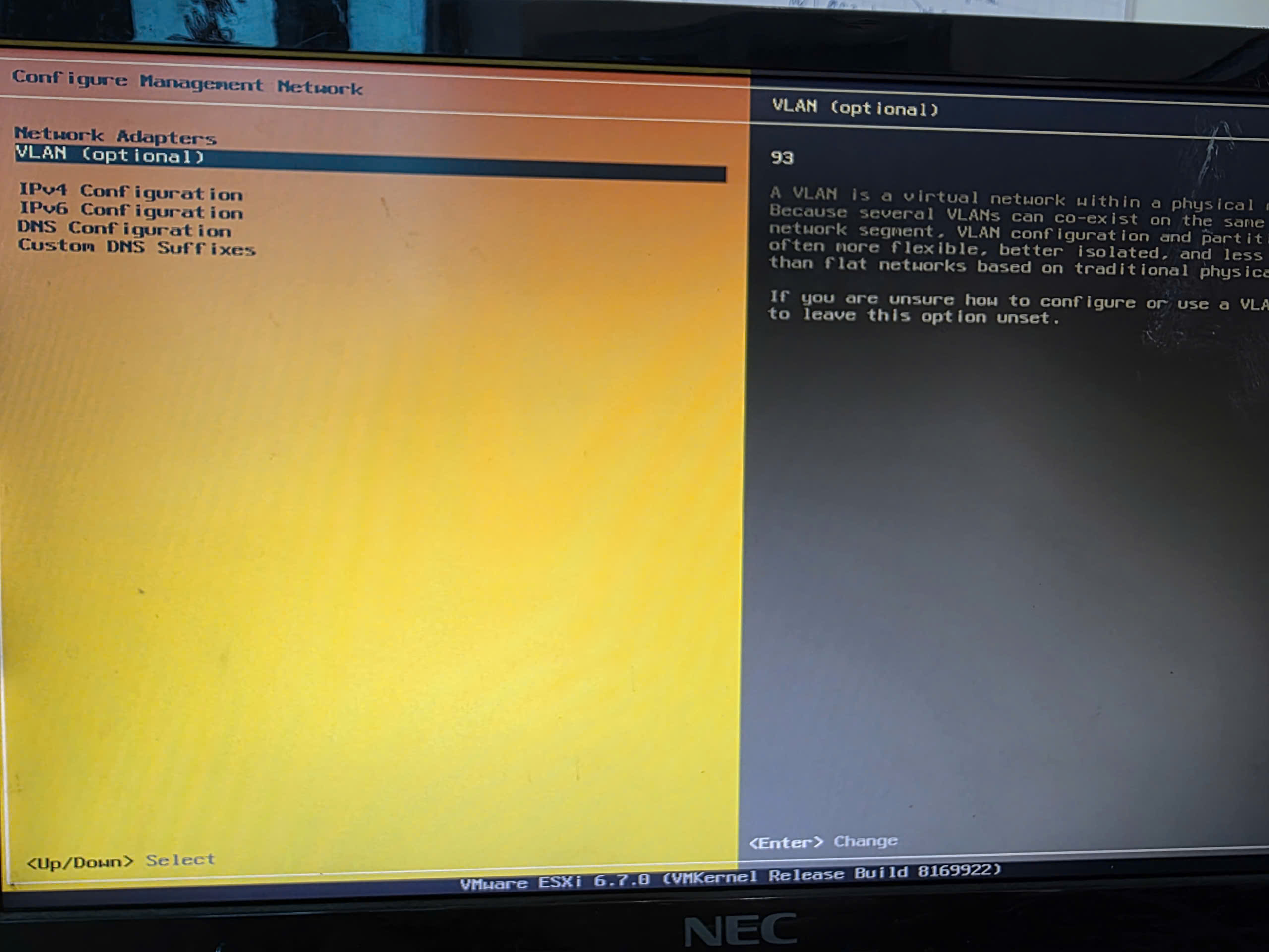
NoteLưu ý Perform this operation identically on both ESXi-01 and ESXi-02 to ensure the Management Network communicates with Switch VLAN 93. Thực hiện thao tác này giống hệt nhau trên cả ESXi-01 và ESXi-02 để đảm bảo mạng Quản trị thông suốt với VLAN 93 trên Switch.
Step 04: Configure ESXi-01 (IP: 10.10.93.201)
Bước 04: Cấu hình ESXi-01 (IP: 10.10.93.201)
Set static IP address for ESXi-01 server via DCUI, then configure Networking and Storage details. Thiết lập địa chỉ IP tĩnh cho máy chủ ESXi-01 thông qua DCUI, sau đó cấu hình chi tiết Mạng và Lưu trữ.
Step 0: Basic Management IP Configuration Bước 0: Cấu hình IP Quản trị cơ bản
- IPv4 Configuration:Cấu hình IPv4: StaticTĩnh (Static)
- IP Address:Địa chỉ IP: 10.10.93.201
- Subnet Mask:Subnet Mask: 255.255.255.0
- Default Gateway:Gateway: 10.10.93.1
-
DNS Configuration:Cấu hình DNS:
- Primary DNS: 8.8.8.8DNS chính: 8.8.8.8
- Hostname: esxi01.doanh.localHostname: esxi01.doanh.local
Verify: From the admin PC, open CMD and Ping 10.10.93.201.
Kiểm tra: Từ máy PC quản trị, mở CMD và Ping 10.10.93.201.
Step 1: Create Port Groups on vSwitch0 Bước 1: Tạo các Port Group trên vSwitch0
Access ESXi Web Client:
Truy cập ESXi Web Client:
https://10.10.93.201
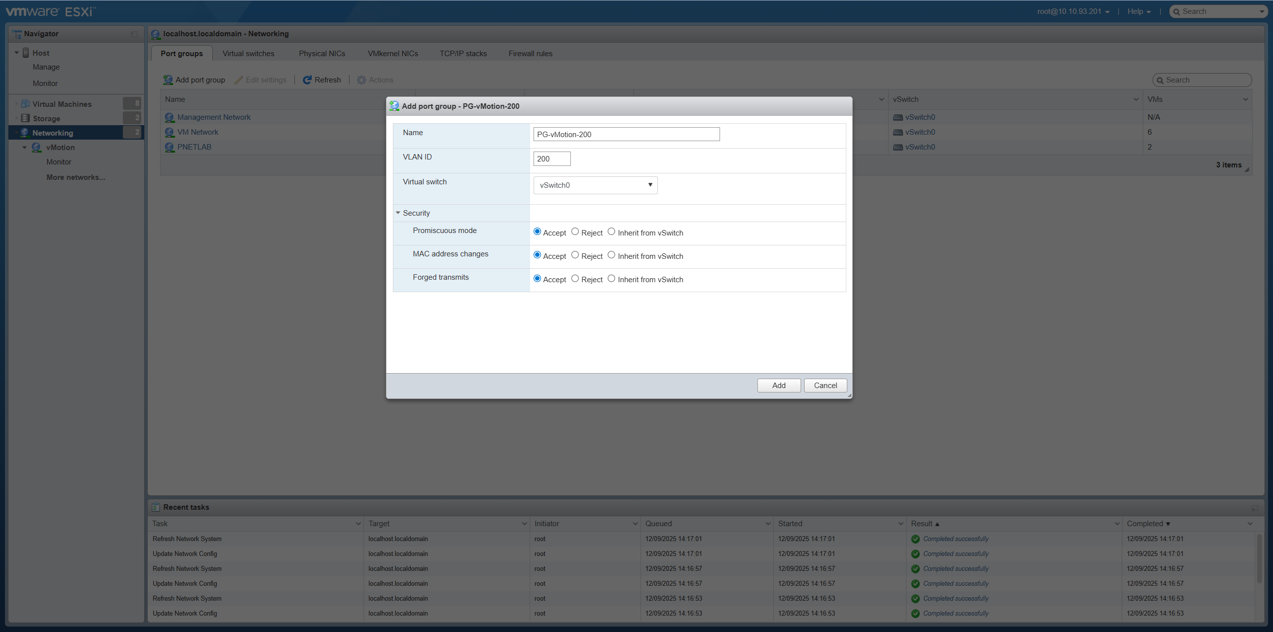
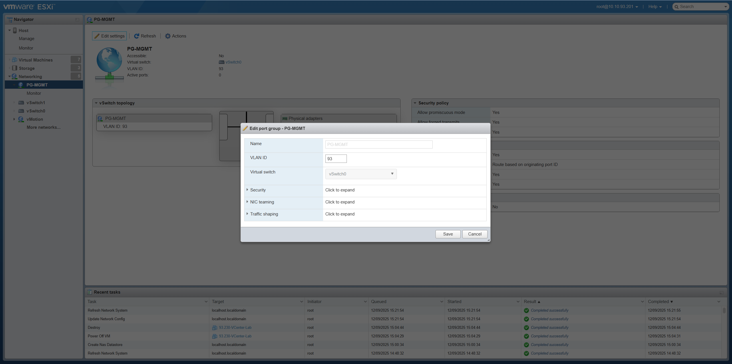
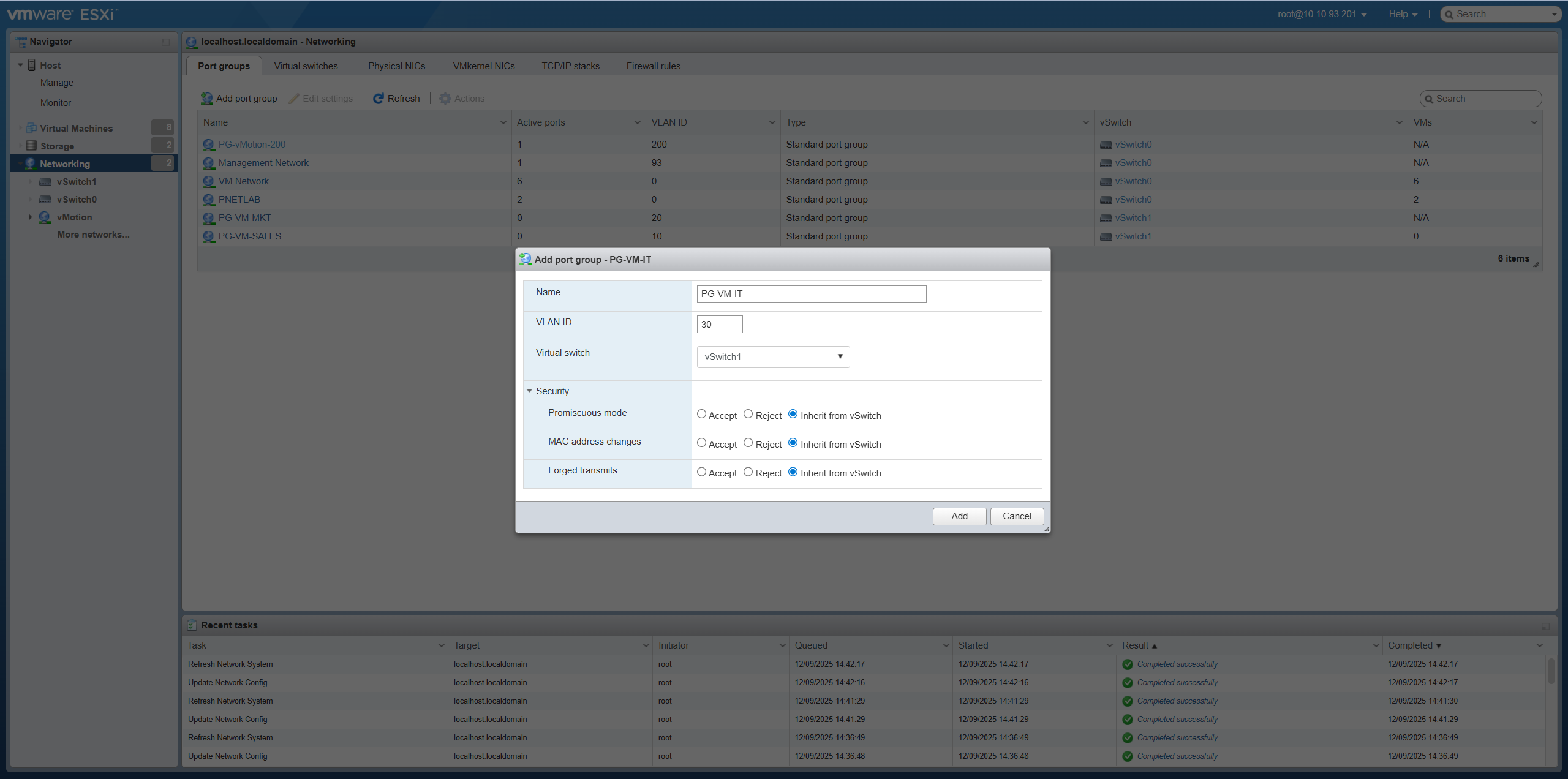
Go to Networking → Port groups: Truy cập Networking → Port groups:
- Create PG-vMotion-200: VLAN ID = 200 on vSwitch0VLAN ID = 200 trên vSwitch0
- Create PG-MGMT-93: VLAN ID = 93 on vSwitch0VLAN ID = 93 trên vSwitch0
NoteLưu ýUnder Security, you do NOT need to enable: Promiscuous mode, MAC address changes, Forged transmits. Trong phần Security, bạn KHÔNG cần bật: Promiscuous mode, MAC address changes, Forged transmits.
Explanation: When to enable? Giải thích: Khi nào cần bật?
- Promiscuous mode: Allows VM to see all traffic. Enable for packet sniffing (Wireshark), IDS/IPS, or Nested ESXi. Cho phép VM thấy toàn bộ gói tin đi qua vSwitch. Bật khi dùng phần mềm bắt gói tin (Wireshark), IDS/IPS hoặc chạy Nested ESXi.
- MAC address changes: Allows guest OS to change its MAC address. Enable for Microsoft NLB or Clustering. Cho phép Guest OS thay đổi MAC khác với ESXi cấp. Bật cho Microsoft NLB hoặc Clustering.
- Forged transmits: Allows sending packets with spoofed source MAC. Enable alongside MAC address changes. Cho phép gửi gói tin với nguồn MAC giả mạo. Thường bật cùng với MAC address changes.
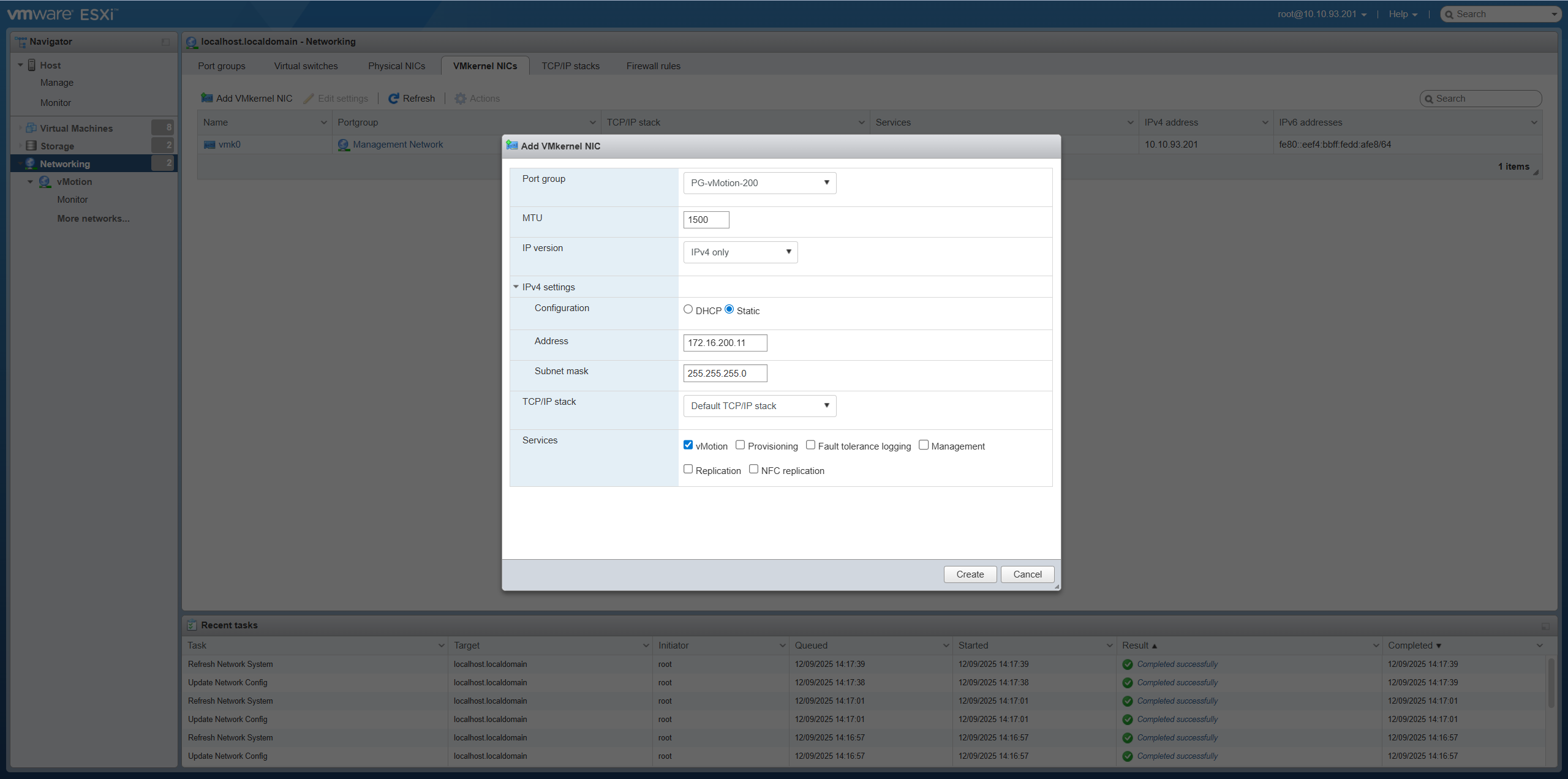
Step 2: Create VMkernel NIC for vMotion Bước 2: Tạo VMkernel NIC cho vMotion
Go to Networking → VMkernel NICs → Add VMkernel NIC: Truy cập Networking → VMkernel NICs → Add VMkernel NIC:
- Port group:Port group: PG-vMotion-200
- IPv4 Settings:IPv4: 172.16.200.11 / 255.255.255.0
- Services:Dịch vụ: ✓ vMotion
Step 3: Verify vMotion connectivity between ESXi-01 and ESXi-02 Bước 3: Kiểm tra kết nối vMotion giữa ESXi-01 và ESXi-02
NoteLưu ý Only perform this ping check after configuring IP for host ESXi-02 (see Step 05). Chỉ thực hiện lệnh ping này sau khi đã cấu hình IP cho host ESXi-02 (xem Bước 05).
Enable SSH on ESXi-01 and perform VMkernel ping check: Bật SSH trên ESXi-01 và thực hiện lệnh ping VMkernel:
[root@localhost:~] esxcli network ip interface list
[root@localhost:~] vmkping -I vmk1 172.16.200.12
PING 172.16.200.12 (172.16.200.12): 56 data bytes
64 bytes from 172.16.200.12: icmp_seq=0 ttl=64 time=0.669 ms
64 bytes from 172.16.200.12: icmp_seq=1 ttl=64 time=0.442 ms
64 bytes from 172.16.200.12: icmp_seq=2 ttl=64 time=0.378 ms
Requirement:Yêu cầu: Ping must be successful before proceeding to the next step. Ping phải thành công trước khi chuyển sang bước tiếp theo.
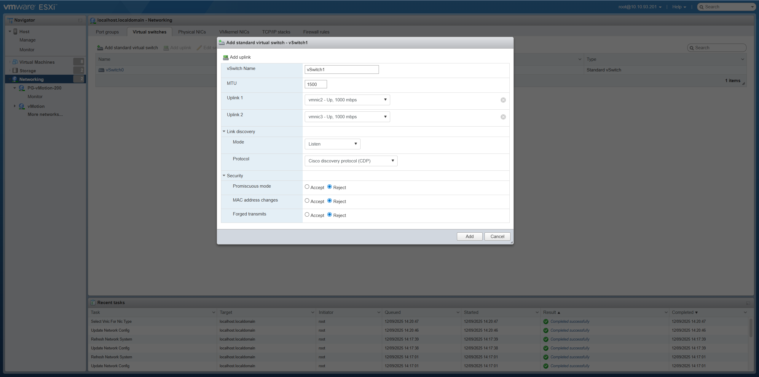
Step 4: Create vSwitch1 for VM Network Bước 4: Tạo vSwitch1 cho VM Network
Go to Networking → Virtual switches → Add standard virtual switch: Truy cập Networking → Virtual switches → Add standard virtual switch:
- Name:Tên: vSwitch1
- Uplink 1:Uplink 1: vmnic2
- Uplink 2:Uplink 2: vmnic3
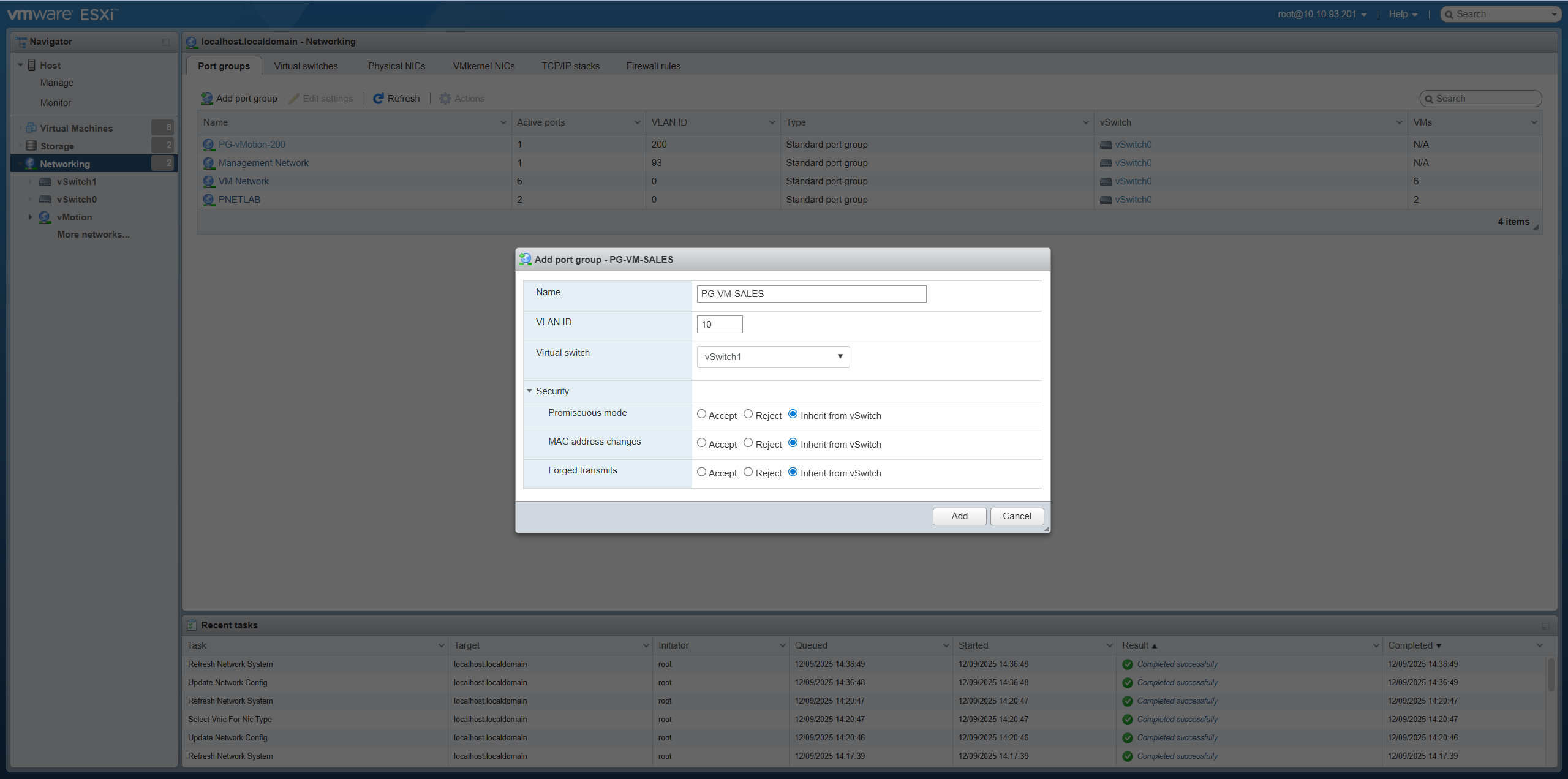
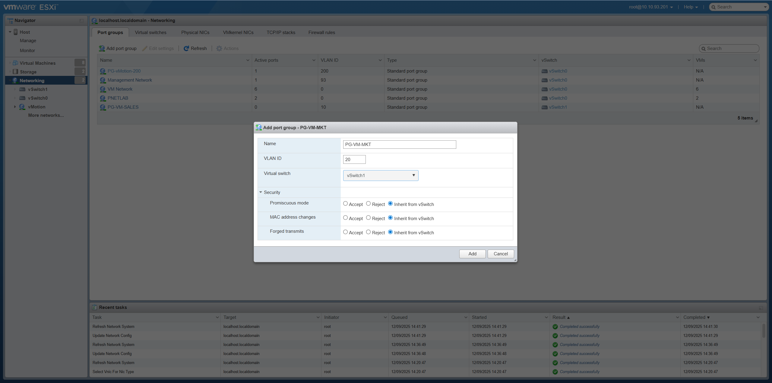
Step 5: Create Port Groups for VM Network Bước 5: Tạo Port Group cho VM Network
Create 3 Port Groups on vSwitch1: Tạo 3 Port Group trên vSwitch1:
-
PG-VM-VLAN10: VLAN ID = 10VLAN ID = 10
-
PG-VM-VLAN20: VLAN ID = 20VLAN ID = 20
-
PG-VM-VLAN30: VLAN ID = 30VLAN ID = 30
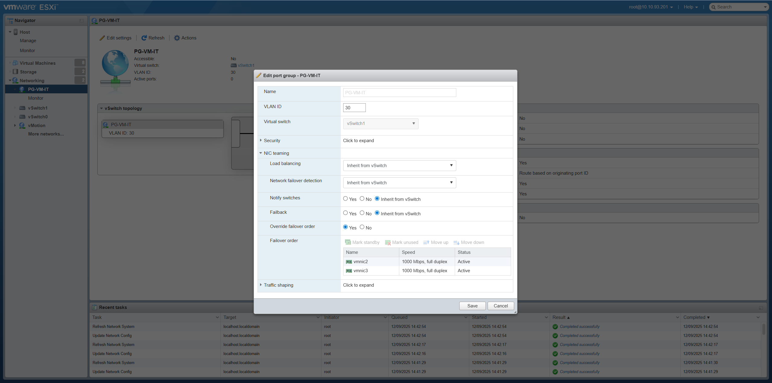
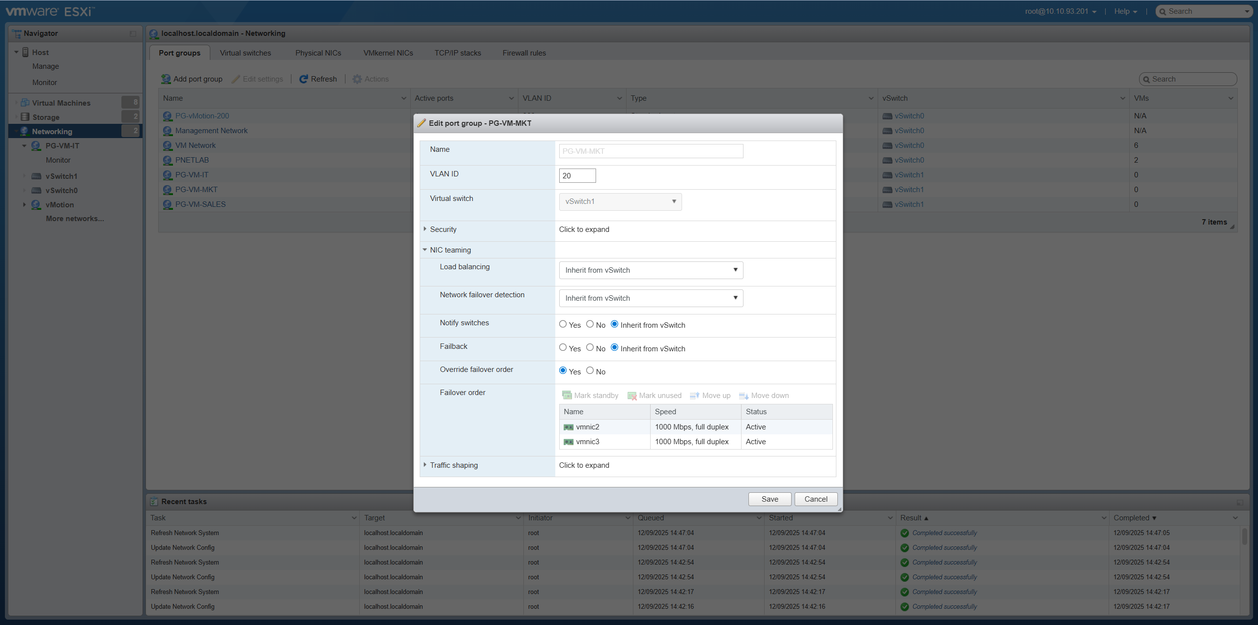
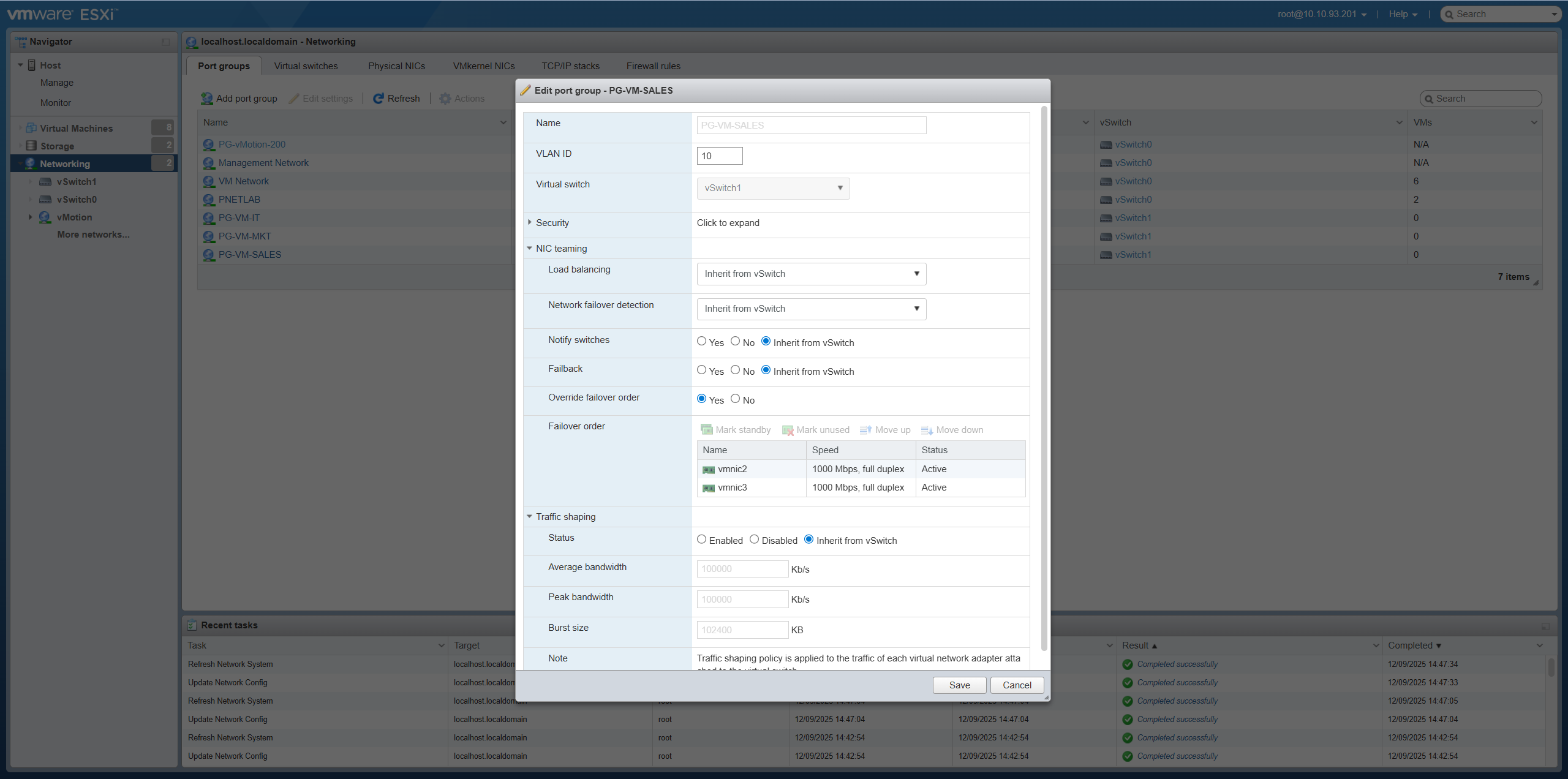
Step 6: Configure Teaming and Failover Bước 6: Cấu hình Teaming và Failover
Edit each created Port Group (PG-VM-VLAN10, PG-VM-VLAN20, PG-VM-VLAN30): Chỉnh sửa từng Port Group đã tạo (PG-VM-VLAN10, PG-VM-VLAN20, PG-VM-VLAN30):
- Go to Edit Settings → Teaming and FailoverVào Edit Settings → Teaming and Failover
- Failover order:Failover order: Override = YesOverride = Yes
- Active uplinks:Active uplinks: vmnic2, vmnic3
- Load balancing:Load balancing: Route based on originating virtual portRoute based on originating virtual port

Step 7: Mount NAS Datastore (Synology) Bước 7: Kết nối NAS Datastore (Synology)
Add Shared Storage from Synology NAS: Thêm Shared Storage từ Synology NAS:
- NAS IP:IP NAS: 10.10.93.190
- Go to Storage → Datastores → New datastoreVào Storage → Datastores → New datastore
- Select Mount NFS datastoreChọn Mount NFS datastore
-
NFS Settings:Thiết lập NFS:
- NFS Server: 10.10.93.190NFS Server: 10.10.93.190
- NFS Share: /volume1/ESXi_Datastore (example)NFS Share: /volume1/ESXi_Datastore (ví dụ)
- Datastore name: NAS_Shared_StorageTên Datastore: NAS_Shared_Storage
- NFS version: NFS 3Phiên bản NFS: NFS 3
✅ Step 04 Complete:Hoàn tất Bước 04: ESXi-01 is ready with full network and storage configuration. ESXi-01 đã sẵn sàng với cấu hình mạng và lưu trữ đầy đủ.